Building a Game Boy Advance multiboot cable
Let's say you're playing around with writing your own games or other homebrew software for the Game Boy Advance. You can run it in an emulator, sure. But what if you want to test it on real hardware?
You could get one of those flash cartridges, like the EZ-FLASH Omega Definitive Edition or the EverDrive GBA Mini. But then you look at the prices...
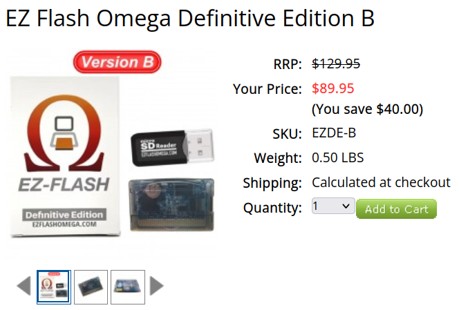
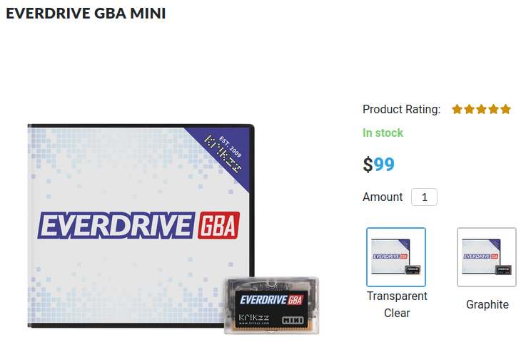
I mean, they're really nice devices. If you just want to play your ahem legally sourced or dumped ahem ROMs, they'll do just fine. But if you just want to mess around with a little homebrew program, $90–$100 is a lot to spend on one of these bad boys. Might as well stick to the emulator...
But wait, did you know that the Game Boy Advance can run programs without a cartridge?
You can send a program over the link port, have the GBA load it into memory, and then run it.[1]
You'll still need a little hardware to connect the computer to the GBA, but the cable is cheap to build. Maybe even under $10, depending on what you pay for the parts and what you've already got lying around. That's a pretty good excuse to build one.
For this one, I used a Raspberry Pi Pico and a cheap GBA game link cable. The hardware is pretty simple. Four wires. Getting those four wires into the right places, though...
Multiboot
If you've played a GBA multiplayer game where everyone shares one cartridge, this is how the other Game Boys get their copy of the program. The GBA with the cartridge sends it over the link cable. The code to receive and start that program is already in the receiving GBA's BIOS.[1]
The fun part is that the sender doesn't have to be another Game Boy. With a suitable interface and some software, a computer can send over a homebrew program instead.
There's a catch, of course. The program gets loaded into the GBA's 256 KiB of external work RAM, so it needs to fit in there. Turn the power off and it's gone. Next time, send it again.[2]
It also needs to be built to run from RAM, with the appropriate multiboot header and entry point. So you can't just grab any cartridge ROM and hope for the best.[1]
Multiboot supports both Normal and Multi-Player transfer modes (there's also Joybus). I went with Normal mode, which needs the serial output, serial input, clock, and ground connections.[1]
The Cable
I used a cheap game link cable like this one. These have the connector we need, but usually don't have all six contacts populated.
The pin numbering is documented on ConsoleMods. Here's their diagram, showing the cable plug on the left and the console port on the right:
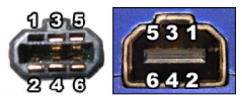
Diagram from ConsoleMods.

| Pin | Signal | Function |
|---|---|---|
| 1 | VDD | Power; unused here |
| 2 | SO | Serial output from the GBA |
| 3 | SI | Serial input to the GBA |
| 4 | SD | Unused for this setup |
| 5 | SC | Serial clock |
| 6 | GND | Ground |
The cheap cables I've come across often have pins 2, 3, 4, 5 on one end and 3, 4, 5, 6 on the other. The connections between them look like this:
| One end | Other end |
|---|---|
| 2 (SO) | 3 (SI) |
| 3 (SI) | 6 (GND) |
| 4 (SD) | 4 (SD) |
| 5 (SC) | 5 (SC) |
Here's the end with pins 3, 4, 5, and 6:
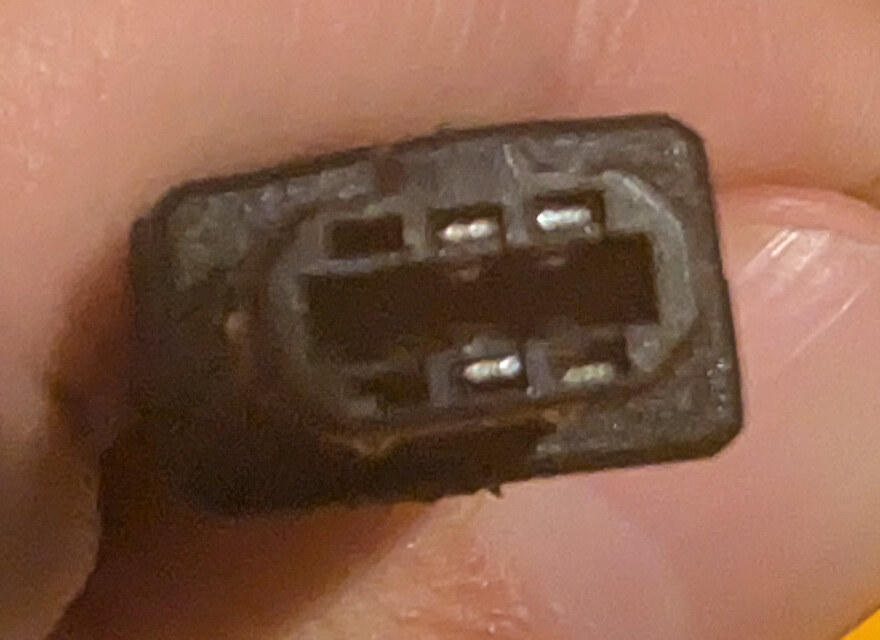
For Normal mode, we need pins 2, 3, 5, and 6. So we already have four wires, but one contact needs to move. Conveniently, we don't need pin 4.
You can use either end of the cable:
- If it has pins 2, 3, 4, 5, move the contact from 4 to 6.
- If it has pins 3, 4, 5, 6, move the contact from 4 to 2.
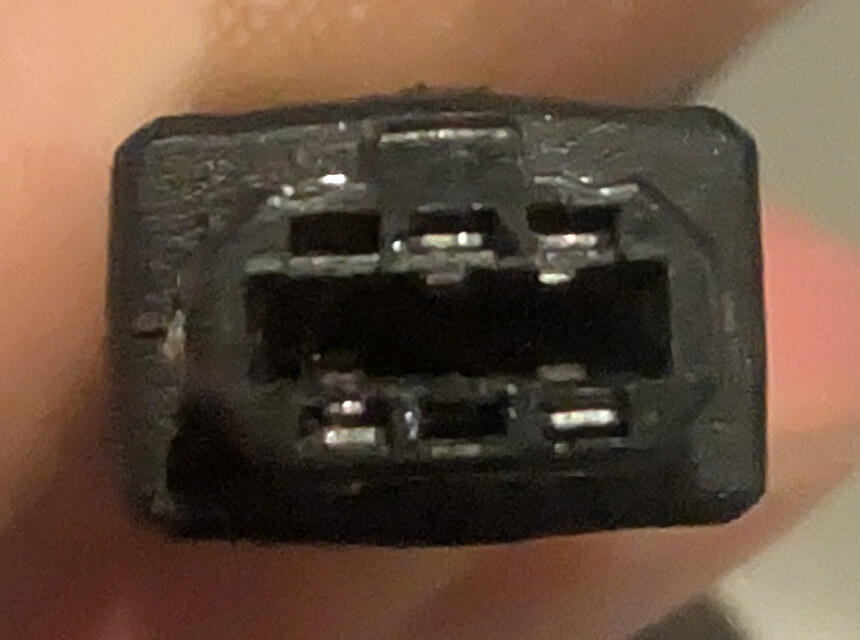
Mine had pins 3, 4, 5, and 6, so I moved the contact from 4 to 2.
Taking It Apart
First, I cut the plastic sleeve so I could pull it back and expose the connector's metal shell.
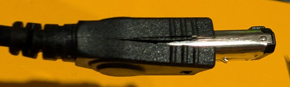
Then I opened up the metal shielding around the inner plastic piece. A couple of small flat-head screwdrivers help here. Go carefully; you'll want to bend it back into shape afterwards.
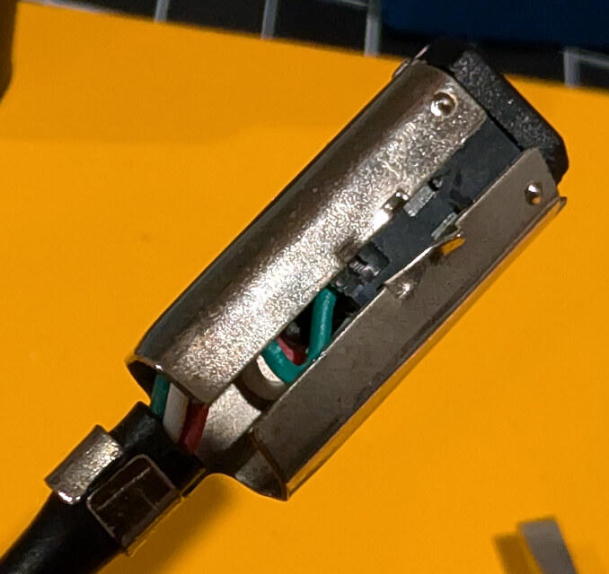
Inside is the plastic piece that actually holds the pins:
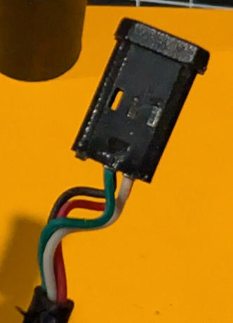
Each pin has a little one-way latch that keeps it from being pulled back out. I figured I could slide a re-pinning tool, or some other thin piece of metal, between the pin and the plastic wall to release the latch.
That was... not very successful.
Looking at it afterwards, I could see that the latch was much closer to where the wires enter. I'd been trying to reach it from the connector tip.
A Little Less Carefully
So I decided to cut a channel into the plastic to help get the pin out. I've done this before and it's worked.
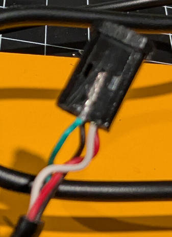
This time, I pulled the wire right out of the crimped pin instead.
Welp.
I ended up yanking the pin out and soldering the wire back onto it.
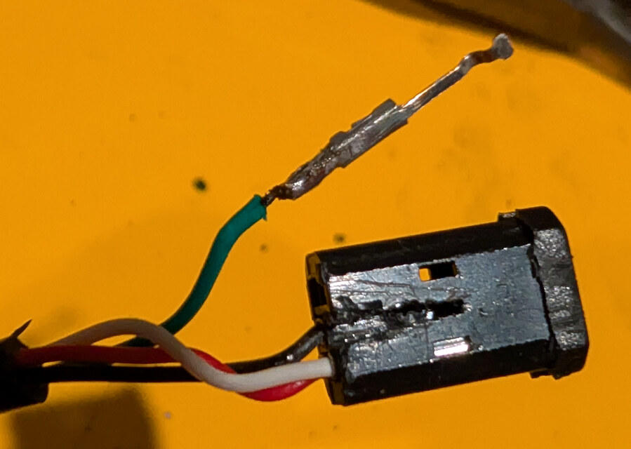
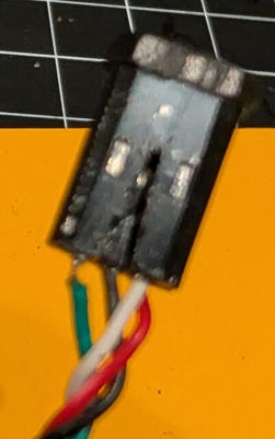
From there, I inserted the pin into position 2. The photo's a little blurry, but here's everything back in place:
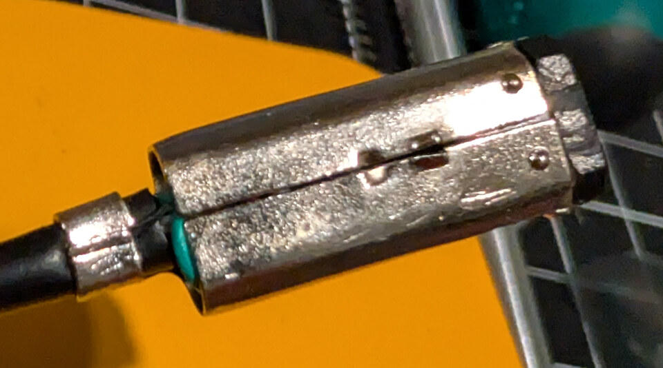
Then I bent the metal shielding back into shape around the plastic holder.
With the sleeve back on, we've got all four contacts in the positions we want:
You can cut off the connector at the other end to expose the wires. Or cut the cable in half and modify both connectors, and you'll have two cables to work with.
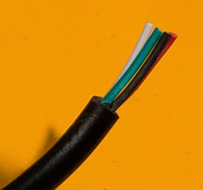
I trimmed the other end and removed a bit of the outer jacket to get at the four wires:
At this point, you're most of the way there.
Use a multimeter in continuity mode to work out which loose wire goes to each contact on the modified plug. Don't rely on wire colors, especially after moving one of the pins. Check for shorts between contacts before connecting it up.
Connecting the Pico
In the past, I've connected the wires directly to a Raspberry Pi and used akkera102/gba_03_multiboot. The wiring for that setup is in gba_01_multiboot:
| GBA | Raspberry Pi B+ |
|---|---|
| 6 (GND) | GND |
| 3 (SI) | GPIO 10 (SPI_MOSI) |
| 2 (SO) | GPIO 9 (SPI_MISO) |
| 5 (SC) | GPIO 11 (SPI_SCLK) |
That worked fine, but copying each new build to the Pi with SCP and then running the upload command over SSH got annoying while testing homebrew.
This time, I had some Raspberry Pi Picos lying around, so I used one of those. The Pico is a little RP2040 microcontroller board that costs about $5. USB on one end, GPIO pins along the sides. Pretty convenient for something like this.
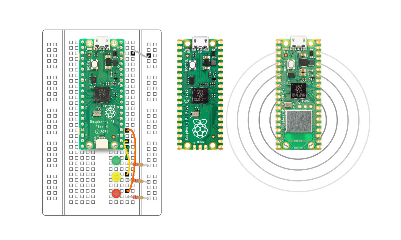
Image from Raspberry Pi. The board in the middle is the original Pico used here.
I wired it like so:
| Pico physical pin | Pico signal | GBA connector pin |
|---|---|---|
| 3 | GND | 6 (GND) |
| 4 | GP2 | 5 (SC) |
| 5 | GP3 | 3 (SI) |
| 6 | GP4 | 2 (SO) |
The first column is the physical board pin number, not the GPIO number. Pico pin 4 is GP2. The official Pico pinout is useful here.
The SI and SO names are from the GBA's perspective: the Pico sends data into the GBA on SI and receives data from it on SO. GP2 provides the clock. Both sides use 3.3V signals, and the ground connection gives them a common reference.
USB powers the Pico, and the GBA uses its own power. GBA pins 1 (VDD) and 4 (SD) are left unconnected.
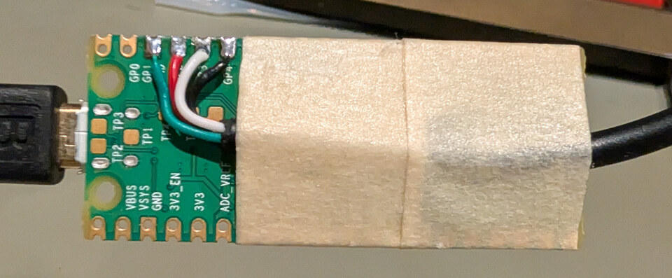
I soldered the four wires directly to the Pico, then taped the cable to the board to keep it from moving around. Nothing fancy.
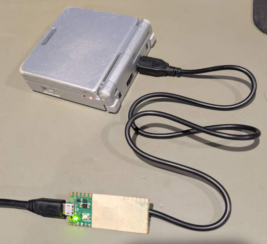
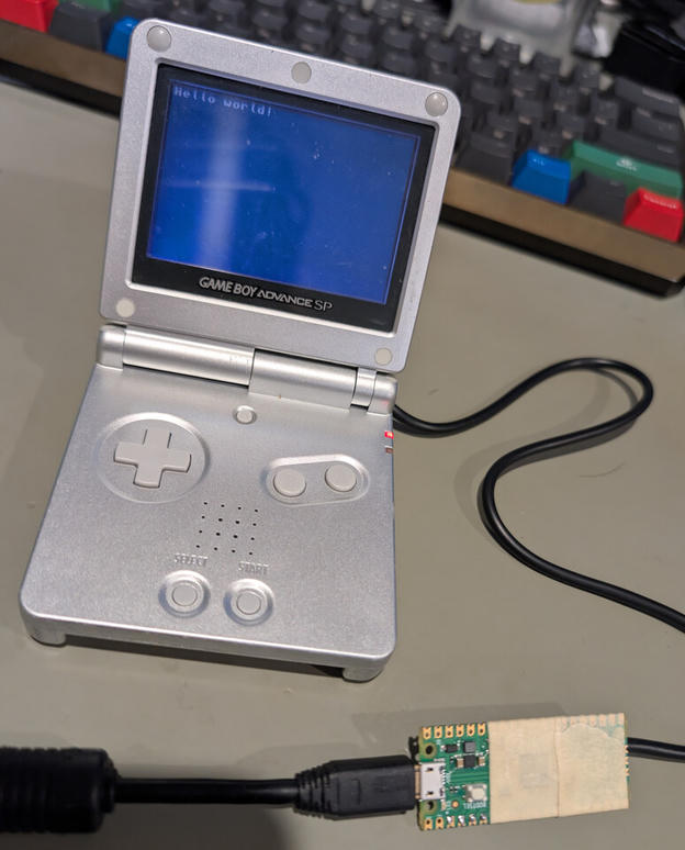
And here's the whole thing connected to a Game Boy Advance SP:
Firmware and Software
The code, along with more details, is in OpenBoyProject/pico-multibooter. The repo contains the Pico firmware, a reusable Rust library called mb-host for talking to the cable, and three PC tools:
mb-cablefinds the cable, checks its firmware, and sends raw data.mb-uploadersends multiboot ROMs to the GBA.mb-dumperreads a cartridge's ROM or save memory through the dumper program running on the GBA.
There are also two GBA programs: the little hello-world test and the cartridge dumper. The PC tools and Pico firmware are written in Rust; the GBA programs are written in C.
Roughly:
Computer -> USB -> Pico -> modified link cable -> GBAWhat's Running on the Pico?
The Pico's job is pretty simple: take words from the computer, clock them out over the link cable, and send the replies back. The multiboot handshake, ROM encryption, and final checksum check all happen in mb-uploader on the PC. The same firmware can then carry commands for a running GBA program, which is how the cartridge dumper uses it.
The firmware uses Embassy for async USB handling and command processing. It runs without the Rust standard library or a heap, using fixed-size buffers. On the computer, it appears as a USB serial device. Commands use a small protocol called PMB3, with CRC-checked frames and batches of up to 256 32-bit words. That way, the PC doesn't need a separate USB request for every word.
The onboard LED is an activity indicator. It's off when idle, lights up while handling a command and sending the reply, and goes off again when that's done. Repeated commands can make it flicker during a transfer. Errors or a disconnect turn it off too.
On the GBA side, the Pico uses its hardware SPI peripheral in mode 3, MSB-first, at a nominal 256 kHz, with no chip-select line. Each word is transferred synchronously, followed by an async wait of at least 36 microseconds to give the GBA time to prepare for the next one. Closing the USB session cancels pending work and clears partial messages. It doesn't reset the GBA, though; restarting a failed upload still means restarting the Game Boy.
Flashing the Pico
For a source build, you'll need Rust and Cargo, a native C linker for the PC tools, and picotool for flashing. The repo's environment setup covers the platform-specific bits. Clone the repo, build the PC tools, and add the Pico's Rust target:
$ git clone https://github.com/OpenBoyProject/pico-multibooter.git
$ cd pico-multibooter
$ cargo build --locked --release
$ rustup target add thumbv6m-none-eabi
$ cargo build-firmware --locked --release
Hold the Pico's BOOTSEL button while plugging it into USB, then release it and flash the firmware:
$ cargo flash --locked --releasebuild-firmware and flash are Cargo aliases defined in the repo. The flash command builds the firmware if needed, then uses picotool to load and start it. This firmware is for the original RP2040 Pico.
If you're using a prebuilt release archive, you can instead copy pico-multibooter.uf2 to the Pico's RPI-RP2 drive in BOOTSEL mode. That route doesn't need a compiler or picotool. Use the firmware and PC tools from the same release, or build them from the same source revision.
Once the Pico restarts, check that the computer can find it and talk to it:
$ cargo cable --release -- list
$ cargo cable --release -- info
info checks the cable's firmware identity, not whether the GBA is connected or ready. On Linux, your account also needs permission to open the serial port; on Debian and Ubuntu, that's usually handled by the dialout group.
Sending a Program
Connect the cable and power on the GBA without a cartridge. If there's a cartridge inserted, hold START + SELECT through the boot logo to enter multiboot mode instead of starting the game.
From the same repository directory:
$ cargo upload --release -- game.gbaReplace game.gba with a multiboot-compatible ROM. The host can automatically select the cable if it finds exactly one matching device. Otherwise, specify the serial port:
$ cargo upload --release -- --port /dev/ttyACM0 game.gba/dev/ttyACM0 is a Linux device path; use the port reported by cargo cable --release -- list on your computer. cargo upload runs mb-uploader. With a release archive, the equivalent command is ./mb-uploader game.gba on Linux/macOS, or .\mb-uploader.exe game.gba in Windows PowerShell.
The upload finishes with a checksum check, so reaching 100% doesn't quite mean it's done. Wait for verification. To upload another program, restart the GBA and put it back into multiboot mode.
To try the included hello-world program, you'll need devkitPro's gba-dev tools, Make, and Python 3. With that environment set up, run these from the repo root:
$ cargo build-gba hello-world
$ cargo upload --release -- gba/hello-world/build/hello-world_mb.gba
cargo build-gba calls the GBA project's Makefile. Release archives include the already-built hello-world_mb.gba if you'd rather skip that part.
Here's a little "Hello world!" test ROM running on the GBA. Sent over the cable, loaded into RAM, and away it goes.
Dumping a Cartridge
Oh yeah, the cable can also be used to dump a cartridge's ROM and save data, either for archival purposes or to play your legally owned games in an emulator. Might as well bring your progress with you.
There's a multiboot program in gba/rom-dumper that runs on the GBA and reads the inserted cartridge. The PC tool, mb-dumper, requests blocks of data, verifies them, and saves them to a file on the computer. Let's start with the ROM.
So the little dumper program has to fit in RAM, but the cartridge ROM can be much larger. The GBA sends it back a piece at a time.
The dumper uses the same devkitPro setup as hello world: devkitARM, libgba, gbafix, Make, and Python 3. Build it from the repo root:
$ cargo build-gba rom-dumperSet DEVKITPRO and DEVKITARM to match your installation. If you're using a release archive, it already includes rom-dumper_mb.gba.
Insert the cartridge before turning on the GBA, then hold START + SELECT through the boot logo. Keep the cartridge inserted and upload the dumper:
$ cargo upload --release -- gba/rom-dumper/build/rom-dumper_mb.gbaOnce the GBA shows GBA ROM Dumper ready..., run the PC dumper. For an 8 MiB cartridge:
$ cargo dump --release -- --size 0x800000 cartridge.gbaWith a release archive, those two commands become ./mb-uploader rom-dumper_mb.gba and ./mb-dumper --size 0x800000 cartridge.gba. Both tools select a single connected cable automatically; add --port if you need to choose one.
The size needs to match your cartridge's ROM. It isn't detected automatically; 0x800000 is just the value for this 8 MiB example. The PC checks each block's CRC before saving it, but that only verifies the transfer. It doesn't tell you whether you've picked the right ROM size.
Pick a new output filename; the dumper won't overwrite an existing file. When everything has been checked and saved, the GBA displays PC verified and saved ROM. An interrupted dump can leave a partial file, so don't mistake that for a finished backup.
Dumping an 8 MiB cartridge takes about 7 minutes with this setup (8MiB through 19.1KiB/s. About 14 minutes for a 16M cartridge dump). Enough time to go make some coffee.
Dumping Save Data
The same GBA program can dump the cartridge's save memory. ROM and save dumps are separate commands, and you can do either one first without uploading the dumper again. You'll need the current v3 GBA dumper and matching PC tool; if you've been using the older v2 image, rebuild and upload it using the steps above.
Patched cartridges: save dumping may not work, and can damage the existing save. Detection checks signatures in the ROM, not the actual save chip. An SRAM-patched cartridge can still have a Flash signature left over. If the dumper mistakes SRAM for 128 KiB Flash, its bank-switch commands become writes to SRAM, overwriting save bytes. A successful transfer CRC won't catch this.
Don't use automatic save detection or guess a Flash override on patched cartridges or ones with an unknown save implementation. Identify the hardware and patch first, and use a dumper that supports them. The sram override only reads 32 KiB; it isn't a general fix for patched 64 KiB saves or custom layouts. See the patched-cartridge notes before trying it.
With the dumper running on the GBA, use --save in place of --size:
$ cargo dump --release -- --save cartridge.savOr, from a release archive:
$ ./mb-dumper --save cartridge.savThe default detection looks for save-library signatures in the cartridge ROM. It recognizes standard SRAM/FRAM saves (32 KiB) and Flash saves (64 or 128 KiB). You don't need to dump the ROM first; the GBA scans it locally.
EEPROM needs a little more help. Its signature doesn't tell us the capacity, so choose eeprom512 for a 512-byte save or eeprom8k for an 8 KiB save, depending on the cartridge. For the latter:
$ cargo dump --release -- --save --save-type eeprom8k cartridge.savThe release binary takes the same flags. There are also sram, flash64, and flash128 overrides for cartridges whose save hardware you know. The save-dumping guide has the details. Don't combine --save with the ROM's --size option.
The GBA first copies the save into RAM, then sends it over with the same block CRC checks as a ROM dump. Detection and preparation can take a few seconds before the percentage starts moving. When it's finished, the GBA shows Save verified and saved on PC.
The resulting .sav is raw cartridge save memory, without RTC data or emulator save-state metadata. Keep the original dump and import a copy into your emulator as cartridge save data, ideally alongside the ROM from the same cartridge. The CRC checks that the transfer arrived intact, not whether the game considers the save valid.
Patched cartridges can also need save conversion and a compatible unmodified ROM for emulator use. Having the ROM and save from the same cartridge doesn't necessarily make them work together in an emulator.
Anyways, that's the cable. Four wires, one moved pin, and a little more persuasion than I originally intended.
Thanks for reading.
73,
-B
-
GBATEK's BIOS Multi Boot documentation covers the transfer protocol and modes. The cartridge header section describes the extra entries used for multiboot programs. ↩ ↩2 ↩3 ↩4
-
Tonc's hardware overview describes the GBA's memory layout and where multiboot programs are loaded. ↩